The scatterplate interferometer is used for testing concave mirrors and gives interferograms that are interpreted the same way as those from a Twyman-Green or laserbased Fizeau. The advantage of this setup is that it is a common path interferometer, so the auxiliary optics' quality is unimportant. A laser can be used as the source, but it is often better to use a spectrally filtered white light source or arc lamp. The spatially filtered light source is imaged onto the test part and the scatterplate is placed near the center of curvature of the test surface so that the scatterplate is reimaged on itself (inverted).

The light transmitted by the scatterplate the second time falls into four categories: (1) unscattered-unscattered, which creates a bright spot; (2) unscattered-scattered, the reference beam; (3) scattered-unscattered, the test beam; and (4) scattered-scattered, a background signal that reduces fringe contrast.
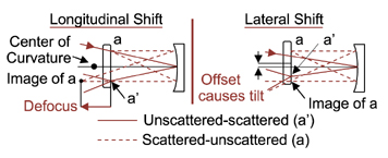
Longitudinal translation of the scatterplate changes defocus and lateral displacement introduces tilt.
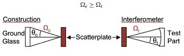
The critical component of this interferometer is the scatterplate, which needs inversion symmetry. This can be done by exposing a photographic plate to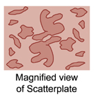 laser speckle from a laser incident on a piece of ground glass, rotating the plate 180°, and superimposing a second exposure of the same speckle. To ensure uniform illumination of the test part from the scattered light, the solid angle of the ground glass seen from the photographic plate during construction of the scatterplate should be at least as large as the solid angle of the test part seen from the scatterplate. The plate should scatter 10 to 20% of the incident light.
PHASE-SHIFTING SCATTERPLATE INTERFEROMETER
The difficulty in improving measurement accuracy by phase shifting with this interferometer is that the test and reference beams traverse nearly the same path, so shifting the scatterplate will not create a path difference. One way to phase shift utilizes a birefringent scatterplate. The scatterplate can be made of calcite, where the side with the scatter pattern and a flat piece of glass create a cavity containing index-matching oil that matches the index of the ordinary index of the calcite at the source wavelength. A spectrally narrow source (laser) is used so the chromatic variations of the polarizationelements have a minimal effect. The first polarizer passes linearly polarizedlight at 45° with respect to the optic axis of the birefringent scatterplate, so half the beam will see the ordinary index of the crystal and not scatter because of the index-matching oil. The other half of the beam will partially scatter due to the index mismatch between the extraordinary index and the oil. The quarter-wave plate at 45° exchanges the two beams so that the unscattered reference beam scatters in the birefringent scatterplate, while the scattered test beam is unscattered on the second pass through the scatterplate. Note that if there is no unwanted scattering of the direct beams there will be no background irradiance term. If all the light scatters for the scattered beam, the hotspot is eliminated.
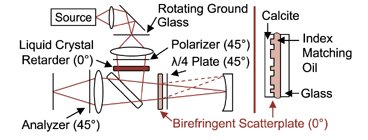
An analyzer at 45° is needed to combine the beams so they interfere. A liquid crystal retarder at 0° before the beamsplitter introduces a variable phase shift between the two beams. This setup performs comparably to a commercial Fizeau interferometer and is limited by the accuracy of the liquid crystal retarder.